This section details the initial steps for setting up your Rotary SPOA10 lift. It outlines the basic preparations and considerations crucial before commencing the physical installation process, ensuring a smooth and safe assembly. Proper planning is essential for a successful installation.
Safety Precautions Before Installation
Before initiating the SPOA10 lift installation, prioritizing safety is paramount. Begin by thoroughly reviewing the entire installation manual, paying close attention to warnings and cautions outlined by Rotary. Ensure the installation area is clear of obstructions and unauthorized personnel. Verify that the concrete foundation meets the minimum thickness and strength requirements specified in the manual to support the lift’s weight and operational loads.
Always wear appropriate personal protective equipment (PPE), including safety glasses, gloves, and steel-toed boots. Disconnect electrical power to the installation site to prevent accidental electrocution. Properly support and secure heavy components during handling to avoid drops or collapses. Never work under the lift until it is fully installed and properly anchored. Be aware of pinch points and moving parts during assembly. If using lifting equipment, ensure it is rated for the load and in good working condition. Adherence to these safety precautions will significantly reduce the risk of accidents and injuries during the installation process.
Tools and Equipment Required
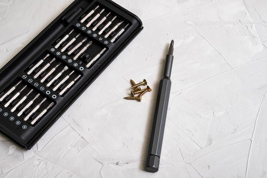
A comprehensive set of tools is essential for a successful SPOA10 lift installation. This includes a heavy-duty rotary hammer drill with appropriate concrete drill bits for anchor bolt installation, ensuring correct hole diameter and depth as specified in the manual. A calibrated torque wrench is crucial for tightening anchor bolts to the precise torque specifications, preventing loosening or over-tightening. Standard wrenches, sockets, and screwdrivers of various sizes are needed for assembling the lift components.
Lifting equipment, such as a forklift or engine hoist, may be required to safely lift and position heavy columns and overhead assemblies. A level and plumb bob are necessary for ensuring accurate vertical alignment of the columns. Measuring tapes and squares are needed for verifying dimensions and clearances. Additionally, hydraulic fluid, typically Dexron III, is required for filling the hydraulic system after installation. Grease is also necessary for lubricating moving parts. Finally, safety glasses, gloves, and steel-toed boots are mandatory PPE for the installer.
Site Preparation and Lift Location
Prior to installing the SPOA10, ensure the site meets specifications. Verify concrete thickness and quality. Reference architect plans to locate the lift properly. Ensure adequate overhead clearance is present; Proper site preparation guarantees safe and effective lift operation.
Bay Layout and Dimensions
Understanding the bay layout and dimensions is crucial for a successful SPOA10 installation. Refer to the manual for precise measurements and spatial requirements. Typical bay layouts are illustrated in Figure 1a, 1b, 1c, and 1d, providing a visual guide for positioning the lift within the workspace. These diagrams showcase the recommended clearances around the lift, ensuring sufficient operating space for vehicles and technicians.
The SPOA10 installation manual specifies the overall height of different lift models, a critical factor when considering ceiling height restrictions. For extra narrow bay settings, specific adjustments may be necessary, such as cutting the bar and cushion. The dimensions provided in the manual are essential for determining the correct placement of the columns and overhead assembly.
Accurate measurements prevent obstructions and ensure compliance with safety regulations. Consider the swing radius of the lift arms and the potential movement of vehicles during operation. Planning the bay layout carefully optimizes workflow and enhances safety in the automotive service environment, enabling efficient and secure lifting procedures.
Column Installation and Mounting
This stage focuses on the secure and accurate placement of the SPOA10 lift columns. Proper column installation is critical for the lift’s stability and safe operation. This includes precise alignment and anchoring to the concrete floor, following torque specifications.
Anchor Bolt Installation and Torque Specifications
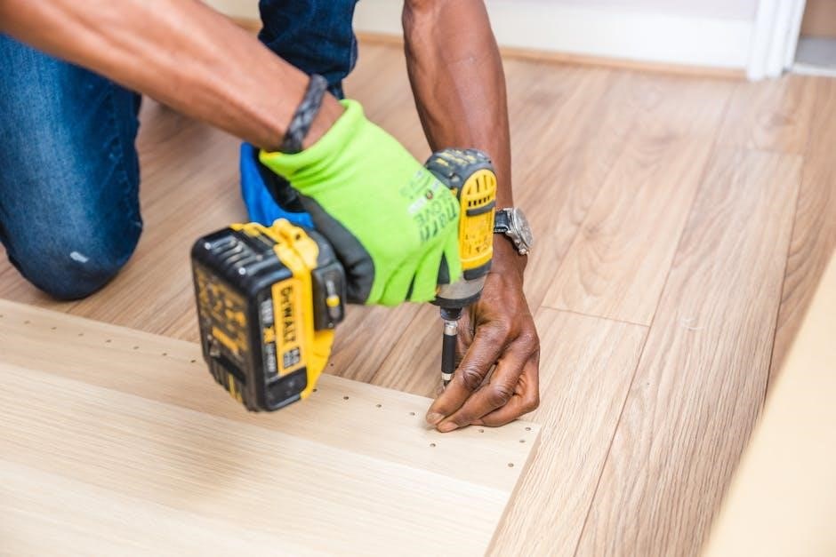
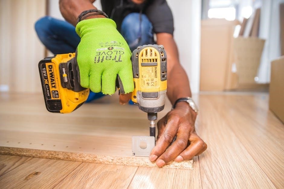
Securing the SPOA10 lift columns properly relies heavily on correct anchor bolt installation. The process begins with drilling holes into the concrete floor, ensuring they match the specified diameter and depth as outlined in the installation manual. It’s crucial to use a hammer drill suitable for concrete and to clean the holes thoroughly after drilling to remove dust and debris, which can compromise the anchor’s grip.
Once the holes are prepared, insert the anchor bolts, making sure they are flush with the base plate of the column. The use of shims might be necessary to ensure the column is plumb. Following this, the anchor bolts must be tightened to the exact torque specifications provided in the SPOA10 installation manual. Typically, this torque is around 110 ft-lbs (149 Nm), but always verify with the manual.
It is crucial to use a calibrated torque wrench to achieve accurate tightening. If an anchor bolt fails to reach the specified torque, it indicates a potential issue with the concrete or the anchor itself. In such instances, the concrete should be assessed, and if necessary, reinforced or replaced before reinstalling the anchor bolts.
Overhead Assembly Installation
The overhead assembly of the SPOA10 lift is a critical step, ensuring proper synchronization and safety during operation. This process involves connecting the overhead beam to the previously installed columns, typically using mounting brackets and hardware as specified in the installation manual. Begin by carefully lifting the overhead assembly into position, ensuring it aligns correctly with the mounting brackets on each column.
Secure the assembly using the provided bolts, flanged locknuts, and star lock washers. The manual specifies the correct size and type of hardware to use, usually 3/8-16NC x 3/4 flanged HHCS bolts. Tighten the bolts according to the torque specifications in the manual. For the SPOA10, the middle holes on the mounting bracket are generally used, while outer holes are reserved for other models like the SPOA7 or SPOA10NB.
Double-check the alignment of the overhead assembly to ensure it is level and square with the columns. Proper alignment is essential for smooth and even lifting. After tightening all hardware, verify that the overhead assembly is securely attached to the columns and that there are no loose connections. This step is vital for the safe and reliable operation of the lift.

Hydraulic and Air Connections
This stage involves connecting the hydraulic and air lines. Ensure all connections are tight and follow the manufacturer’s instructions. Use Dexron III or equivalent fluid. Properly connect the lines to avoid leaks and ensure safe lift operation during use.
Filling and Bleeding the Hydraulic System
After connecting the hydraulic lines, the next critical step involves filling the hydraulic reservoir with the correct fluid. Use Dexron III or an equivalent hydraulic fluid as recommended by Rotary Lift. Ensure the reservoir is filled to the appropriate level, as indicated in the manual, avoiding overfilling or underfilling, which can affect performance.
Bleeding the hydraulic system is essential to remove any trapped air, which can cause erratic lift operation and reduce lifting capacity. Locate the bleed screws or valves on the hydraulic cylinders. Open the bleeder valves and allow the air to escape while slowly cycling the lift up and down. Continue this process until only hydraulic fluid emerges from the bleed points, indicating all air has been purged from the system.
Regularly check the hydraulic fluid level after bleeding and top off as needed. Proper filling and bleeding of the hydraulic system are crucial for the safe and efficient operation of the SPOA10 lift, ensuring smooth and reliable performance for years to come.
Final Adjustments and Testing
With the hydraulic and electrical connections complete, the SPOA10 lift requires careful final adjustments and thorough testing to ensure safe and reliable operation. Begin by checking the arm restraints for proper engagement and release. Adjust the restraints as needed so that they lock securely when the lift is raised and release smoothly when lowered.
Next, perform a full range of motion test, raising and lowering the lift several times to verify smooth and consistent operation. Observe the lift for any signs of binding, uneven movement, or unusual noises. Carefully inspect all hydraulic connections for leaks and tighten fittings as necessary.
Load test the lift by gradually increasing the weight on the lift arms, up to the rated capacity. Monitor the lift’s performance under load, checking for any signs of instability or structural weakness. Ensure the safety locks engage properly at various heights. After load testing, re-inspect all connections and components for any signs of stress or damage. These adjustments are vital for safe operation.
Post-Installation Checklist and Maintenance
Following the successful installation and testing of your SPOA10 lift, a comprehensive post-installation checklist is crucial for ensuring long-term reliability and safety. Begin by thoroughly reviewing all installation steps, verifying that each procedure was completed according to the manual. Confirm that all bolts are properly torqued and all connections are secure.
Next, develop a regular maintenance schedule to keep your lift in optimal condition. This should include daily visual inspections for any signs of damage, wear, or leaks. Lubricate all moving parts, such as the arm pivots and roller bearings, according to the manufacturer’s recommendations. Periodically check the hydraulic fluid level and condition, replacing it as needed. Inspect the cables and pulleys for wear and tear, replacing them if necessary.
Keep a detailed record of all maintenance activities, including dates, tasks performed, and any parts replaced. This documentation will be invaluable for troubleshooting future issues. Proper maintenance is essential for a long lift lifespan.